My wiring diagram is shown below. I have been driving the car trouble-free for several months with this in place.
FocusEV Wiring
As I progressed with my conversion I did quite a bit of research on how others have wired up their vehicles. There are a lot of examples available on the Internet. In the days before the World Wide Web there would have been a lot more trial and error (and probably a lot of things blown up!) Since I'm an electrical engineer I also have enough knowledge to come up with some wiring ideas on my own, but others have already done almost all of them in a similar fashion. The goal was to create a control circuit that allows the electrical system to turn on and operate safely, even if faults occur in one or more components. I also want a vehicle that can be driven by other drivers without knowledge specific to an electric vehicle.
One area where I recently made some additions is in protecting the motor from over-revving. As I understand it, allowing the motor to be powered when there's no load can result in some pretty bad things, like complete motor destruction! Rather than confirming this the hard way (through personal experience) I decided to add some safeguards. I use existing switches (clutch and brakes) to remove power from the motor immediately if either pedal is depressed. I had hoped to prevent the motor from getting power when the car was in neutral, but the factory wiring manual lied to me - this signal is not available from the transaxle. Otherwise the factory wiring manual has come in very handy figuring out how to wire up the car.
My Wiring Diagram
My wiring diagram is shown below. I have been driving the car trouble-free for several months with this in place.
The Control Box
Below is a picture of the control box as I was putting it together.
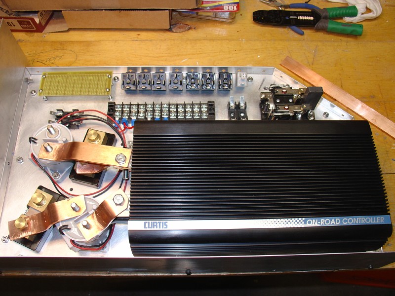
The components are mounted on a 1/4 inch thick aluminum plate and I've built a box around the whole thing with aluminum sides and a clear polycarbonate cover. The box contains the Curtis controller, two contactors, two shunts for measuring battery current and motor current, fuses, the heater contactor, and eight automotive relays for the control circuit. The box won't be completely water-tight but will keep the components safe from rain or road spray.
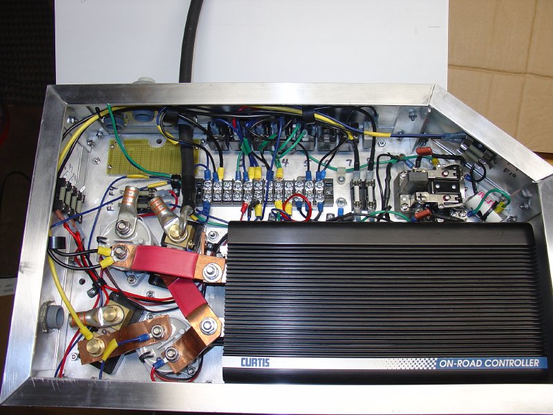
Here's another picture of the control box before I put it in the car. Cramped, but an efficient use of space in the limited area under the hood.
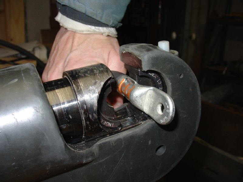
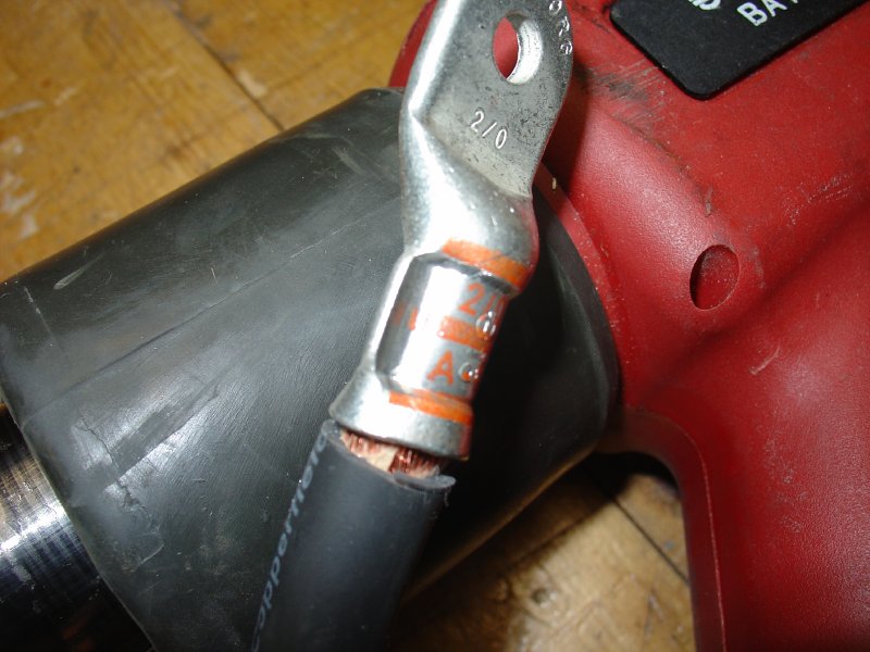
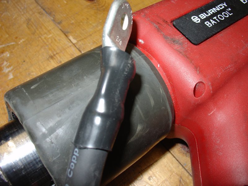
Making Battery Cables
I borrowed a power crimper from a local EV enthusiast. (It's called the Burndy "Batool" - but even Batman doesn't have one of these babies!) This will save me a LOT of work, since all I have is a crude hammer-crimper. I tried this power tool out on 2/0 gauge wire with one of the lugs for the controler. Here are some pictures of the crimp and the heatshrink.
Updated 14NOV2009 CHS